

 Technical Information Power And Control Cables Power Appendixes Guide to the Wiring Regulations Domestic protective equipotential bonding layouts
 Page Domestic protective equipotential bonding layouts
| Domestic protective equipotential bonding layouts | |
|
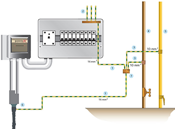
This section provides diagrams of typical protective equipotential bonding layouts. It has been added to provide further guidance on typical layouts of bonding conductors, and also assists with recognizing earthing arrangements. Many other layouts are, of course, possible. Figure 1. shows the main earthing terminal connected via the earthing conductor to the utility cut-out stud terminal (TN-C-S). Figure 2. shows the main earthing terminal connected via the earthing conductor to the sheath of the utility supply cable (TN-S). Figure 3. shows the main earthing terminal connected via the earthing conductor to the installation earth electrode (TT). The earthing conductor in a TT installation may only need to be 6 mm2 although it is shown as 16 mm2 in this diagram. |
|
 |
 |
| Figure 1. | Figure 2. |
 |
Supplementary equipotential bonding : |
| Figure 3. | |